Home › Unlabelled ›
Brake Controller Wiring Diagram - Diagram Hayman Reese Trailer Brake Controller Wiring Diagram Full Version Hd Quality Wiring Diagram Anewiring Argiso It / Auxiliary connection is optional, it may be connected to any 12v to 24v constant power source or left unconnected.
Brake Controller Wiring Diagram - Diagram Hayman Reese Trailer Brake Controller Wiring Diagram Full Version Hd Quality Wiring Diagram Anewiring Argiso It / Auxiliary connection is optional, it may be connected to any 12v to 24v constant power source or left unconnected.. Important facts to remember 1. The trailer lighting system must not be directly spliced into your tow. Important facts to remember 1. The wiring harness shown is typical of any electric brake control installation. Read the following instructions carefully before installing and/or operating the brake control.
The trailer lighting system must not be directly spliced into your tow. Husky towing 17929 towed vehicle light kit. Select a different vehicle to begin a new search. A brake controller wiring installation kit makes light work! Keep these instructions with the brake control for future reference.
Ford Electric Brake Wiring Wiring Diagram Name Left High A Left High A Agirepoliticamente It from www.etrailer.com Trailer brake controllers and vehicle wiring. Elecbrakes is designed to operate 1 to 2 braked axles; Elecbrakes is a popular choice for trailer users across a range of applications. Tell us why it wasn't helpful and we'll work on making it better: Do not disturb the position of the switch. Important facts to remember 1. Mounting and wiring the unit is a task that many users can do themselves. Husky towing 13189 towed vehicle wiring kit.
Tail light converters brake control wiring vehicles towed behind a motorhome wiring diagram for common plugs breakaway switches.
You almost certainly know already that primus brake controller wiring diagram is among the top issues online. Elecbrakes is designed to operate 1 to 2 braked axles; This vehicle is designed not just to travel one location to another but also to carry heavy loads. Some newer vehicles provide their own brake control jumper harness which makes the install a plug and play affair. It reveals the components of the circuit as streamlined shapes, as well as the power as well as signal links between the tools. The wiring diagram to the right is a basic brake controller hook up. Using larger/longer screws may damage the unit. Select a location for the brake controller under the dashboard in a central location where the driver's knee will not strike it. A brake controller wiring installation kit makes light work! Generic wiring diagram read this first: The trailer lighting system must not be directly spliced into your tow. Duplex wire, 20 amp circuit breaker and attaching terminals. Electric brake controller wiring diagram.
Some newer vehicles provide their own brake control jumper harness which makes the install a plug and play affair. Keep these instructions with the brake control for future reference. Ddec ii controls jake brake® models 71/92a wiring diagram ddec series ii (2 mode) control group p/n 017363 +12v red green orange grn/yel purple gray connect ground to negative battery post or engine frame rail insulate end of orange wire purple and gray wires may be used by some vehicle manufacturers. The brake control must be installed with a 12 volt negative ground system. The 2030 mark 12 is an older tekonsha model;
Venturer Brake Controller Wiring Diagram from i0.wp.com Read the following instructions carefully before installing and/or operating the brake control. Generic wiring diagram read this first: Special light and wiring systems need to be installed on your tow vehicle before you can tow any trailer. Do not disturb the position of the switch. Purchase a wiring harness specific to your vehicle application from your vehicle's manufacturer, and plug that harness into the recommended connection portal. Typical vehicle brake control wiring diagram. This husky towing towed vehicle wiring kit is a plug and play. This vehicle is designed not just to travel one location to another but also to carry heavy loads.
Assortment of tekonsha brake controller wiring diagram.
Using larger/longer screws may damage the unit. The brake control must be installed with a 12 volt negative ground system. Do not disturb the position of the switch. Read and follow all instructions carefully before wiring brake control. A wiring diagram is a simplified traditional photographic depiction of an electrical circuit. You almost certainly know already that primus brake controller wiring diagram is among the top issues online. The wiring diagram to the right is a basic brake controller hook up. This vehicle is designed not just to travel one location to another but also to carry heavy loads. Tail light converters brake control wiring vehicles towed behind a motorhome wiring diagram for common plugs breakaway switches. Trailer brake controllers and vehicle wiring. Wellborn collection of prodigy brake controller wiring diagram. It shows the components of the circuit as simplified shapes, and the capacity and signal contacts between the devices. Break away systems may be added to the service brake circuit.
A wiring diagram is a simplified traditional photographic depiction of an electrical circuit. Read the following instructions carefully before installing and/or operating the brake control. Select a location for the brake controller under the dashboard in a central location where the driver's knee will not strike it. Splice down line from the switch; If you would like to give some information about your vehicle, i could make a more specific recommendation on how to wire it and let you know if any other parts are needed.
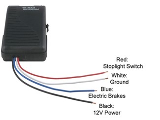
Wiring Diagram For Brake Control Download Scientific Diagram from www.researchgate.net Duplex wire, 20 amp circuit breaker and attaching terminals. It shows the components of the circuit as simplified shapes, and the capacity and signal contacts between the devices. Do not disturb the position of the switch. Each component should be placed and linked to other parts in particular manner. The red (stoplight) wire must be connected to the cold side of the brake pedal stoplight switch. Splice down line from the switch; Using larger/longer screws may damage the unit. October 4, 2018 by larry a.
Primus brake controller wiring diagram (nov 16, ) ―
The trailer lighting system must not be directly spliced into your tow. Elecbrakes is a popular choice for trailer users across a range of applications. Generic wiring diagram read this first: Read the following instructions carefully before installing and/or operating the brake control. You almost certainly know already that primus brake controller wiring diagram is among the top issues online. All brake controllers wire pretty much the same with a white ground wire, a black power wire a red brake switch wire and a blue brake feed wire that goes to the trailer brakes. Read and follow all instructions carefully before wiring brake control. The 2030 mark 12 is an older tekonsha model; It shows the elements of the circuit as simplified forms, as well as the power and also signal connections between the devices. The following diagram is a general guide for wiring common brake controllers into cars. Keep these instructions with the brake control for future reference. Select a different vehicle to begin a new search. The blue (brake output) wire must be connected to the trailer connector's brake wire.