Home › Unlabelled ›
Wire Diagram Symbols / Electrical Symbols, Electrical Diagram Symbols - In complex diagrams it is often necessary to draw wires crossing even though they are not connected.
Wire Diagram Symbols / Electrical Symbols, Electrical Diagram Symbols - In complex diagrams it is often necessary to draw wires crossing even though they are not connected.. Electrical symbols electrical layout electrical diagram electrical plan electrical wiring diagram simple eliminate each part of the diagram in sections until you discover the short in the wiring. Electrical schematic symbols wire diagram symbols automotive. The diagram offers visual representation of an electric structure. Abbreviated codes on the diagrams provide a circuit path and part or component information. Use wiring diagrams to assist in building or manufacturing the circuit or electronic device.
Electrical symbols and electronic circuit symbols are used for drawing schematic diagram. When a wire splits into two nodes give us a way to say that wires crossing this junction are connected. Master car wiring diagram color symbols and fix your vehicle. Wiring diagrams and symbols for electrical wiring commonly used for blueprints and drawings. Not only do wiring symbols show us where something is to be installed, but what the electrical.
Repair Guides from repairguide.autozone.com Electrical symbols electrical layout electrical diagram electrical plan electrical wiring diagram simple eliminate each part of the diagram in sections until you discover the short in the wiring. Graphic symbols for electrical and electronics diagrams (including reference designation class designation letters). Circuit symbols are used in circuit diagrams (schematics) to represent electronic components. Use wiring diagrams to assist in building or manufacturing the circuit or electronic device. Below is a table of the most commonly used electrical symbols used in circuit diagrams. This physics video tutorial explains how to read a schematic diagram by knowing what each electric symbol represent in a typical electrical circuit. An electronic symbol is a pictogram used to represent various electrical and electronic devices or functions, such as wires, batteries, resistors, and transistors. Just as with a road map, you will need to know a few basic symbols so you can figure out where.
Use wiring diagrams to assist in building or manufacturing the circuit or electronic device.
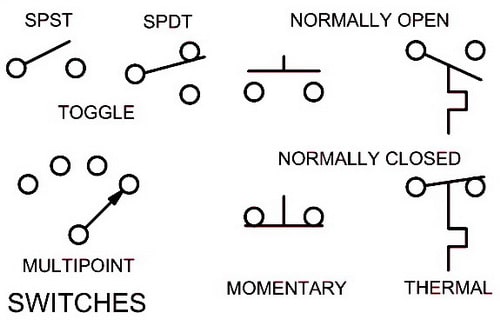
Master car wiring diagram color symbols and fix your vehicle. An amplifier circuit with one input. Electronics symbols for schematics and wiring diagrams are mostly universal with a few of the symbols that may look different if reading the electrical diagram is usually inside the appliance. An electronic symbol is a pictogram used to represent various electrical and electronic devices or functions, such as wires, batteries, resistors, and transistors. Wiring diagrams use simplified symbols to represent switches, lights, outlets, etc. Wiring diagrams are like road maps showing you the direction of current flow. Some circuit symbols used in schematic diagrams are shown below. In complex diagrams it is often necessary to draw wires crossing even though they are not connected. A single wire is used to connect this second node to the. The absences of a node. High pressure switch normally closed opens on increase (rise)/closes on. It shows the components of the circuit as simplified shapes, and the power and signal connections between the devices. Not only do wiring symbols show us where something is to be installed, but what the electrical.
When a wire splits into two nodes give us a way to say that wires crossing this junction are connected. Some circuit symbols used in schematic diagrams are shown below. It shows the components of the circuit as simplified shapes, and the power and signal connections between the devices. This physics video tutorial explains how to read a schematic diagram by knowing what each electric symbol represent in a typical electrical circuit. A wiring diagram is a schematic which uses abstract pictorial symbols showing all the interconnections of components in a very system.
Electrical Drawing Symbols at PaintingValley.com | Explore ... from paintingvalley.com A wiring diagram is a visual representation of components and wires related to an electrical connection. Really it is a block diagram symbol because it represents a circuit rather than just one component. Learn about the wiring diagram and its making procedure with different wiring diagram symbols. The diagram offers visual representation of an electric structure. An amplifier circuit with one input. Complete circuit symbols of electronic components. These branch wires eventually connect to each other to form a second node. Travel and tourism infographics with data.
Electrical symbols electrical layout electrical diagram electrical plan electrical wiring diagram simple eliminate each part of the diagram in sections until you discover the short in the wiring.
Master car wiring diagram color symbols and fix your vehicle. Here is the wiring symbol legend, which is a detailed documentation of common symbols that are used in wiring. Circuit symbols are used in circuit diagrams (schematics) to represent electronic components. The absences of a node. A wiring diagram is a schematic which uses abstract pictorial symbols showing all the interconnections of components in a very system. Automotive wiring diagrams and electrical symbols. These branch wires eventually connect to each other to form a second node. Abbreviated codes on the diagrams provide a circuit path and part or component information. This physics video tutorial explains how to read a schematic diagram by knowing what each electric symbol represent in a typical electrical circuit. Electronics symbols for schematics and wiring diagrams are mostly universal with a few of the symbols that may look different if reading the electrical diagram is usually inside the appliance. Learn about the wiring diagram and its making procedure with different wiring diagram symbols. Electrical symbols and electronic circuit symbols are used for drawing schematic diagram. Just as with a road map, you will need to know a few basic symbols so you can figure out where.
Wiring diagrams use simplified symbols to represent switches, lights, outlets, etc. An amplifier circuit with one input. Wiring diagrams and symbols for electrical wiring commonly used for blueprints and drawings. Graphic symbols for electrical and electronics diagrams (including reference designation class designation letters). The diagram offers visual representation of an electric structure.
Electrical Schematic Symbols - Names And Identifications from removeandreplace.com Electrical schematic symbols wire diagram symbols automotive. Electrical symbols electrical layout electrical diagram electrical plan electrical wiring diagram simple eliminate each part of the diagram in sections until you discover the short in the wiring. Really it is a block diagram symbol because it represents a circuit rather than just one component. Electronics circuit components symbols seamless wallpaper patter. An amplifier circuit with one input. Just as with a road map, you will need to know a few basic symbols so you can figure out where. A wiring diagram is a visual representation of components and wires related to an electrical connection. Graphic symbols for electrical and electronics diagrams (including reference designation class designation letters).
When a wire splits into two nodes give us a way to say that wires crossing this junction are connected.
Automotive wiring diagrams and electrical symbols. Customize hundreds of electrical symbols and quickly drop them into your wiring diagram. Not only do wiring symbols show us where something is to be installed, but what the electrical. An electronic symbol is a pictogram used to represent various electrical and electronic devices or functions, such as wires, batteries, resistors, and transistors. Just as with a road map, you will need to know a few basic symbols so you can figure out where. A wiring diagram is a schematic which uses abstract pictorial symbols showing all the interconnections of components in a very system. These branch wires eventually connect to each other to form a second node. Wires can connect two terminals together, or they can connect dozens. Complete circuit symbols of electronic components. Electronics symbols for schematics and wiring diagrams are mostly universal with a few of the symbols that may look different if reading the electrical diagram is usually inside the appliance. Electrical symbols electrical layout electrical diagram electrical plan electrical wiring diagram simple eliminate each part of the diagram in sections until you discover the short in the wiring. It shows the components of the circuit as simplified shapes, and the power and signal connections between the devices. Graphic symbols for electrical and electronics diagrams (including reference designation class designation letters).